Site-to-Site VPN with Cisco ASA

Site-to-site VPN connections are deployed in order to securely bridge two distant local area networks together across the internet. Cisco ASA appliances achieve this by using the IPsec protocol suite, coupled with either the IKEv1 (RFC4945) or IKEv2 (RFC5996) protocol in order to form and maintain a security association (SA) and pass traffic, bringing the following key advantages:
- Confidentiality: Traffic going across the internet as part of this setup is encrypted, making it more difficult for malicious parties to eavesdrop on it.
- Data Integrity: The data that is sent is hashed and verified by the other side to ensure it wasn't tampered with.
- Authentication: The data is encrypted as per the negotiation parameters and a shared secret. In the case of the IKEv2 standard, a local shared secret and remote shared secret must be defined.
- Anti-Replay Support: Avoids hackers injecting or making changes in packets that travel from a source to a destination.
IKEv2 was released in September 2010 and provides several key improvements over the older standard, which can be found here. In a nutshell, IKEv2 is more secure, less demanding on network and hardware resources and also has built-in support for NAT traversal.
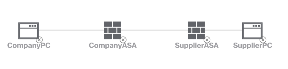
For the purposes of this post, we will be using a set of virtual Cisco ASA appliances running in Cisco Modeling Labs (CML) to establish an IKEv2 based tunnel between my network and a hypothetical supplier's network. The supplier needs access to a specific subnet of mine (192.168.0.0/24) in order to manage some proprietary equipment. The network exposed on the supplier's side will be 192.168.1.0/24. Our ASA will have the IP 10.0.0.1 and the supplier's ASA will be on 10.0.0.2, connected with each other on GigabitEthernet0/0.
Setting the Stage
Within CML, drag two ASAv instances into your lab, connect them with each other on GigabitEthernet0/0 and start them. Configure the interfaces as shown below. You may need to issue a no shut on both interfaces in order for them to become active.
interface GigabitEthernet0/0
 nameif outside
 security-level 0
 ip address 10.0.0.1 255.255.255.0
!
interface GigabitEthernet0/1
 nameif inside_1
 security-level 100
ip address 192.168.0.1 255.255.255.0interface GigabitEthernet0/0
nameif outside
security-level 0
ip address 10.0.0.2 255.255.255.0
!
interface GigabitEthernet0/1
nameif inside_1
security-level 100
ip address 192.168.1.1 255.255.255.0Once done, verify connectivity between the two vASA instances:
CompanyASA# ping 10.0.0.2
Type escape sequence to abort.
Sending 5, 100-byte ICMP Echos to 10.0.0.2, timeout is 2 seconds:
!!!!!
Success rate is 100 percent (5/5), round-trip min/avg/max = 1/2/10 msSupplierASA# ping 10.0.0.1
Type escape sequence to abort.
Sending 5, 100-byte ICMP Echos to 10.0.0.1, timeout is 2 seconds:
!!!!!
Success rate is 100 percent (5/5), round-trip min/avg/max = 1/2/10 msNext, drag two Alpine Linux instances into your lab and attach one to each ASA on port GigabitEthernet0/1. At this point you can either assign the Linux instances a static IP in our respective ranges, or you may wish to setup a small DHCP server on each ASA using the dhcpd command:
CompanyASA(config)# dhcpd address 192.168.0.2-192.168.0.254 inside_1
CompanyASA(config)# dhcpd dns 8.8.8.8 interface inside_1
CompanyASA(config)# dhcpd enable inside_1SupplierASA(config)# dhcpd address 192.168.1.2-192.168.1.254 inside_1
SupplierASA(config)# dhcpd dns 8.8.8.8 interface inside_1
SupplierASA(config)# dhcpd enable inside_1A quick verification on both PCs:
localhost:~$ ip addr sh
1: lo: <LOOPBACK,UP,LOWER_UP> mtu 65536 qdisc noqueue state UNKNOWN qlen 1000
    link/loopback 00:00:00:00:00:00 brd 00:00:00:00:00:00
    inet 127.0.0.1/8 scope host lo
       valid_lft forever preferred_lft forever
    inet6 ::1/128 scope host
       valid_lft forever preferred_lft forever
2: eth0: <BROADCAST,MULTICAST,UP,LOWER_UP> mtu 1500 qdisc pfifo_fast state UP qlen 1000
    link/ether 52:54:00:01:17:3b brd ff:ff:ff:ff:ff:ff
    inet 192.168.1.2/24 scope global eth0
       valid_lft forever preferred_lft forever
    inet6 fe80::5054:ff:fe01:173b/64 scope link
valid_lft forever preferred_lft foreverlocalhost:~$ ip addr sh
1: lo: <LOOPBACK,UP,LOWER_UP> mtu 65536 qdisc noqueue state UNKNOWN qlen 1000
link/loopback 00:00:00:00:00:00 brd 00:00:00:00:00:00
inet 127.0.0.1/8 scope host lo
valid_lft forever preferred_lft forever
inet6 ::1/128 scope host
valid_lft forever preferred_lft forever
2: eth0: <BROADCAST,MULTICAST,UP,LOWER_UP> mtu 1500 qdisc pfifo_fast state UP qlen 1000
link/ether 52:54:00:19:e1:90 brd ff:ff:ff:ff:ff:ff
inet 192.168.0.2/24 scope global eth0
valid_lft forever preferred_lft forever
inet6 fe80::5054:ff:fe19:e190/64 scope link
valid_lft forever preferred_lft foreverAlright! With the current setup, each ASA can interfact with the respective PC that is connected to it on GigabitEthernet0/1. However, due to the security-level of the outside interface being set to 0 (as it should be), neither side can see each other's internal networks - a ping from the supplier's PC to the PC on our side will fail. If the security-level was equal to the one of the inside interface, they would be able to see each other, but the traffic would be vulnerable as it is not encrypted.
Establishing Trust
The security level on the outside interface is set to zero because traffic originating from the open internet is inherently not trustworthy. To ensure that only trustworthy traffic can pass this restriction, we will need to provide the means to negotiate a secure VPN tunnel. This consists of a so-called phase 1 and phase 2. The first phase is responsible for negotiating the connection, the second is for passing traffic.
In the first phase the ASAs will exchange secret keys, authenticate each other and will then proceed to negotiate the IKE security policy. Next, they perform an authenticated Diffie-Hellman exchange in order to check whether the shared secret keys match, and if successful, the tunnel is established and ready for the next phase.
I'm going to go with AES-256 for encryption, SHA for integrity verification and will use Diffie-Hellman group 14 (AES-256) for shared secret verification, with a lifetime of one day. The Cisco ASA offers a wide variety of encryption standards that you can choose from, but keep in mind that some can be pretty resource intensive on your firewall. You're also going to want to stay away from deprecated standards such as 3DES.
crypto ikev2 policy 10
 encryption aes-256
 integrity sha
 group 14
 prf sha
lifetime seconds 86400Except for prf sha, the configuration is actually similar to the IKEv1 policy setup. PRF is the Pseudo Random Function algorithm which is the same as the integrity algorithm.
Next, we need to define an IPsec proposal - this sets the tunnel's encryption mechanism:
crypto ipsec ikev2 ipsec-proposal MY_PROPOSAL
 protocol esp encryption aes-256
protocol esp integrity sha-256What are we tunneling today?
The decision on what kind of traffic ultimately gets tunneled rests on an access-list, which defines which local IP range should have access to which tunneled subnet.
CompanyASA(config)# access-list LAN1_LAN2 extended permit ip 192.168.0.0 255.255.255.0 192.168.1.0 255.255.255.0SupplierASA(config)# access-list LAN2_LAN1 extended permit ip 192.168.1.0 255.255.255.0 192.168.0.0 255.255.255.0If you want to tunnel multiple subnets, you can define an object-group within the access-list instead of an IP range:
SupplierASA(config)# access-list LAN2_LAN1 extended permit ip 192.168.1.0 255.255.255.0 object-group MyClientNetworksCrypto Maps
Now we have to configure a so-called crypto map that combines the access-list, remote peer and IKEv2 proposal together, attaching it to our outside interface in preparation for phase 2 of the process:
CompanyASA(config)# crypto map MY_CRYPTO_MAP 1 match address LAN1_LAN2
CompanyASA(config)# crypto map MY_CRYPTO_MAP 1 set peer 10.0.0.2 CompanyASA(config)# crypto map MY_CRYPTO_MAP 1 set ikev2 ipsec-proposal MY_PROPOSAL
CompanyASA(config)# crypto map MY_CRYPTO_MAP interface outsideSupplierASA(config)# crypto map MY_CRYPTO_MAP 1 match address LAN2_LAN1
SupplierASA(config)# crypto map MY_CRYPTO_MAP 1 set peer 10.0.0.1 SupplierASA(config)# crypto map MY_CRYPTO_MAP 1 set ikev2 ipsec-proposal MY_PROPOSAL
SupplierASA(config)# crypto map MY_CRYPTO_MAP interface outsideThe next step is to configure a tunnel group. This is where we define authentication and the pre-shared-keys, as well as setting the tunnel IPsec mode to LAN to LAN (l2l):
CompanyASA(config)# tunnel-group 10.0.0.2 type ipsec-l2l
CompanyASA(config)# tunnel-group 10.0.0.2 ipsec-attributes
CompanyASA(config-tunnel-ipsec)# ikev2 local-authentication pre-shared-key TESTING1234
CompanyASA(config-tunnel-ipsec)# ikev2 remote-authentication pre-shared-key TESTING5678SupplierASA(config)# tunnel-group 10.0.0.1 type ipsec-l2l
SupplierASA(config)# tunnel-group 10.0.0.1 ipsec-attributes
SupplierASA(config-tunnel-ipsec)# ikev2 local-authentication pre-shared-key TESTING5678
SupplierASA(config-tunnel-ipsec)# ikev2 remote-authentication pre-shared-key TESTING1234Lastly, on both ASAs, we will need to enable IKEv2 on each outside interface:
crypto ikev2 enable outsideRouting
With the tunnels now configured, the last step remaining is to define a route on each firewall that teaches them how to reach each other's inside interfaces / exposed subnets:
CompanyASA(config)# route outside 192.168.1.0 255.255.255.0 10.0.0.2SupplierASA(config)# route outside 192.168.0.0 255.255.255.0 10.0.0.1Testing Connectivity
The tunnels themselves aren't up until there is some activity that matches the access-list that we defined earlier. Via the Alpine Linux PC we recently created on the supplier's side, let's try to ping the PC on our side:
localhost:~$ ping 192.168.0.2 -c 3
PING 192.168.0.2 (192.168.0.2): 56 data bytes
64 bytes from 192.168.0.2: seq=0 ttl=42 time=3.671 ms
64 bytes from 192.168.0.2: seq=1 ttl=42 time=3.439 ms
64 bytes from 192.168.0.2: seq=2 ttl=42 time=8.380 ms

--- 192.168.0.2 ping statistics ---
3 packets transmitted, 3 packets received, 0% packet loss
round-trip min/avg/max = 3.439/5.163/8.380 ms
... and vice versa:
localhost:~$ ping 192.168.1.2 -c 3
PING 192.168.1.2 (192.168.1.2): 56 data bytes
64 bytes from 192.168.1.2: seq=0 ttl=42 time=2.983 ms
64 bytes from 192.168.1.2: seq=1 ttl=42 time=3.456 ms
64 bytes from 192.168.1.2: seq=2 ttl=42 time=2.383 ms

--- 192.168.1.2 ping statistics ---
3 packets transmitted, 3 packets received, 0% packet loss
round-trip min/avg/max = 2.383/2.940/3.456 ms
Success! The site-to-site VPN connection between our two Cisco ASA firewalls is working.